Have you ever wondered how they accurately show stairs on floor plans? Stairs are challenging to draw, but it’s key for home building, renovations, or designing. This guide will show you how to read and understand the stairs on architectural drawings with ease.
Key Takeaways
- Floor plans use standardised symbols and conventions to represent stairs, allowing clear communication between professionals and homeowners.
- Stairs can be shown in various ways, including as a series of parallel lines with arrows to indicate the direction of travel.
- Specific dimensions and calculations are crucial for ensuring stairs meet safety and building code requirements.
- Understanding how to read and interpret floor plan symbols, including those for stairs, is essential for anyone involved in home construction or design.
- Consulting with professionals can help homeowners navigate the complexities of floor plans and ensure their projects are executed safely and efficiently.
Ready to learn how to depict stairs on floor plans accurately? We’ll show you how to represent these important architectural features clearly.
Understanding Floor Plans
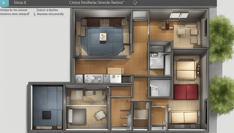
A floor plan is key in architecture and building. It shows a top view of a building’s inside. It’s drawn to scale, giving a cut of the structure at 4 feet high. This shows how walls, doors, windows, and furniture are arranged.
What is a Floor Plan?
A floor plan is a flat drawing of how a building’s inside is arranged. It lets people like architects, builders, and homeowners talk and work together well. They can plan and build with a clear picture of their design.
Different Views in Architecture
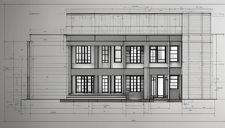
In architecture, there are different ways to look at a building’s design. Plan view, elevation view, and section view show various angles of the building. They help us understand the structure and its parts better.
Plan View
The plan view, or floor plan, gives a top-down look at the building’s inside. It shows where rooms, doors, and windows are. This view helps us see the building’s layout and use of space.
Elevation View
The elevation view shows the building’s outside from the side. It’s a vertical view, great for understanding its height and look. You can see how windows and doors are placed in this view too.
Section View
The section view cuts through the building to see inside. It lets us look at the building’s layers, like walls and floors. We can understand how different parts of the building are stacked up.

Architectural Line Weights and Conventions
In architectural floor plans, different line thicknesses are used, known as line weights. This system makes the plan easier to understand. It helps show the connection between the 2D drawing and the actual 3D building.
Objects Below 4 Feet
Things lower than 4 feet on a floor plan use thin or medium continuous lines. This group includes items like furniture and appliances. They’re what you’d see at your eye level.
Objects Cut at 4 Feet
At the 4-foot height, you’ll find walls and ceilings. They use thicker lines, usually in black. This makes them stand out more since they’re crucial parts of the plan.
Objects Above 4 Feet
Above 4 feet, elements not usually seen are drawn with fine dashed lines. These could be things like ceiling designs. They’re not visible on the plan’s surface view.
Other Uses of Line Weights
Line weights also help with more than just showing heights. They give importance to different parts of the structure. For example, walls are thicker, while furniture might use thinner lines.
Various line types are used too. Solid lines are for visible elements. Dashed lines are for ones you can’t see. And there are lines with long and short dashes for reference points. These all work together to show how a building is structured and used.

Representing Walls on Floor Plans
Walls play a key role in floor plans. They’re shown in distinct ways. The thickness of exterior walls varies. It depends on the local climate, insulation needs, and the siding’s weight. Usually, masonry walls are thicker than those with light siding.
Exterior Walls
Exterior walls are a building’s outer boundary. On floor plans, they’re drawn with thick, solid lines. The width of these lines reflects the wall’s real thickness. Thick lines show heavy materials like bricks or concrete. Meanwhile, lighter materials like siding are shown with thinner lines.
Partitions (Interior Walls)
Interior walls are sketched with lines thinner than those for the outer walls. They divide a building’s inside areas. The line thickness might change. It depends on how the wall is built and the soundproofing needed.
Walls Not Reaching the Ceiling
Open-concept spaces or areas with half-height dividers have unique walls. These walls are drawn as dashed lines on plans. It means they don’t go all the way to the ceiling.
Structural Elements
Besides walls, floor plans also show structural parts. These include foundation walls, bearing walls, and support columns. They secure the building’s frame. You can spot them by their thicker continuous lines.
How to Show Stairs on a Floor Plan
Stairs can be tricky to show on a floor plan because they’re complex. For stair representation, we look at the stairway’s width, the landing, and the tread length. The details in a floor plan guide us on these.
Stair Vocabulary
Knowing stair terms is key to reading a floor plan. Terms like step, handrail, thread, riser, and banister are important. They help us describe different stair elements.
Types of Stairways
Floor plans show many stair types, including straight-run stairs and spiral stairs. The type of stairs in a plan depends on the house’s design and layout. This variety makes each home unique.
Stairs Up
For stair direction, “UP” is written at the start of the stairs. It often includes an upward arrow. This makes it clear which way the stairs go, showing the space’s vertical movement.
Drawing Stairs on Floor Plans
Stairs are drawn differently depending on the floor. They can start, end, or connect different levels. Special line styles show where each part of the stairs is. Drawing stairs this way shows their exact location.
Annotating Stairs
Annotations are used to give more stair information on a floor plan. They include arrows, step numbers, and measurements. These details are essential for understanding the layout of stairs.
Calculating Stair Dimensions
It’s vital to measure stairs correctly for safety and ease of use. Stairs have the riser, which is the step’s vertical face. The tread is the flat part you step on. Lastly, the nosing is the edge of the step that hangs over the riser.
Stair Components
Stairs need to meet certain measurements according to building codes. For instance, treads should be at least 10 inches wide. Risers, on the other hand, shouldn’t be taller than 7.75 inches. The nosing at the edge must be between 0.75 and 1.25 inches. In multi-level construction projects, using systems like concrete stairs formwork can help builders meet these specs more efficiently while speeding up installation and reducing error.
Stair Calculations
The Blondel Formula sets that 2 Risers plus 1 Tread equals about 25 inches total. There’s also the additional comfort rule which says the total of a riser and a tread should be near 18 inches.
If you keep risers at about 7 inches high, a home with a floor-to-floor height of 10 ft 8 in may need around 19 steps. This fits a standard rule for riser height.
Local Code Requirements
Building codes also specify other stair dimensions and safety rules. For example, there should be at least 6 ft. 8 inches of headroom at the top of the stairs. The stairs themselves need to be at least 36 inches wide.
For stairs over 30 inches high, there must be guards that are at least 34 inches tall. Handrails should be between 34 and 38 inches high from the stair surface. They should also be wide enough for a good grip.
It’s essential to follow these rules to keep stairs safe, especially in public places. Not obeying can mean trouble and danger, showing why it’s crucial to stick to the regulations when designing and building stairs.
Floor Plan Symbols and Legends
Understanding a detailed floor plan can feel overwhelming without knowing the symbols. These symbols include walls, doors, windows, stairs, and furniture. They help communicate ideas between architects, builders, and homeowners easily.
Common Floor Plan Symbols
Door symbols show what kind of door is there, like a curve for a triple hinge door. Windows are shown differently too, with sliding ones as three rectangles and casement as mini doors. Stairs are shown as rectangles for straight or sections around a central pole for curved ones.
Wall symbols use thicker lines for interior walls and double lines or thin outlines for exteriors. Materials like brick use specific patterns. Appliance symbols look like the actual appliances, with hidden ones shown using dots.
Plumbing items like toilets are drawn from above. HVAC symbols show things like air conditioning units. Electrical symbols show where lights and outlets go, with a key to explain each one.
Furniture symbols include things like sofas and beds, drawn to scale. They can have detailed drawings for sales too. Living rooms may have many symbols, like sofas and tables.
Understanding Floor Plan Scale
Getting the scale right is key in understanding a floor plan’s size. A legend usually shows the ratio of the drawing to the real size. For example, 1/8 inch might mean 1 foot in reality. Knowing the scale helps with accurate measurements and planning, including where furniture goes.
Reading and Interpreting Floor Plans
To understand a floor plan, look at the room setups and size. Notice how each space flows into the next. Also, focus on where doors, windows, and stairs are placed.
Get used to the symbols and signs used in floor plans. Thick lines often show walls, and doors show which way they swing. Stairs have arrows for their direction, and windows are simple blocks with open direction marks.
Size and scale of the plan are important. Always check the scale to see the true size of rooms and furniture. Look for dimension strings to find how big certain parts are.
Think about how the plan’s design affects the use of space. Imagine your daily activities in the rooms. Consider ceiling height and light, and where furniture could go. You can also ask architects or designers for advice on making the best of the plan.
Conclusion
Understanding how to read and interpret floor plan symbols is key for those in home construction, renovation, or design. These symbols show the layout and functionality of a building. This helps architects, builders, and homeowners work together well. They can make their dreams come true.
The architectural symbols in floor plans include stairs, windows, furniture, and appliances. Knowing these symbols helps homeowners understand what their space will look like. This lets them make smart choices during home construction or renovation.
Learning to read floor plan symbols gives homeowners more control over their house design. They can better ensure the final look meets their needs and style.
